LAB II
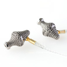
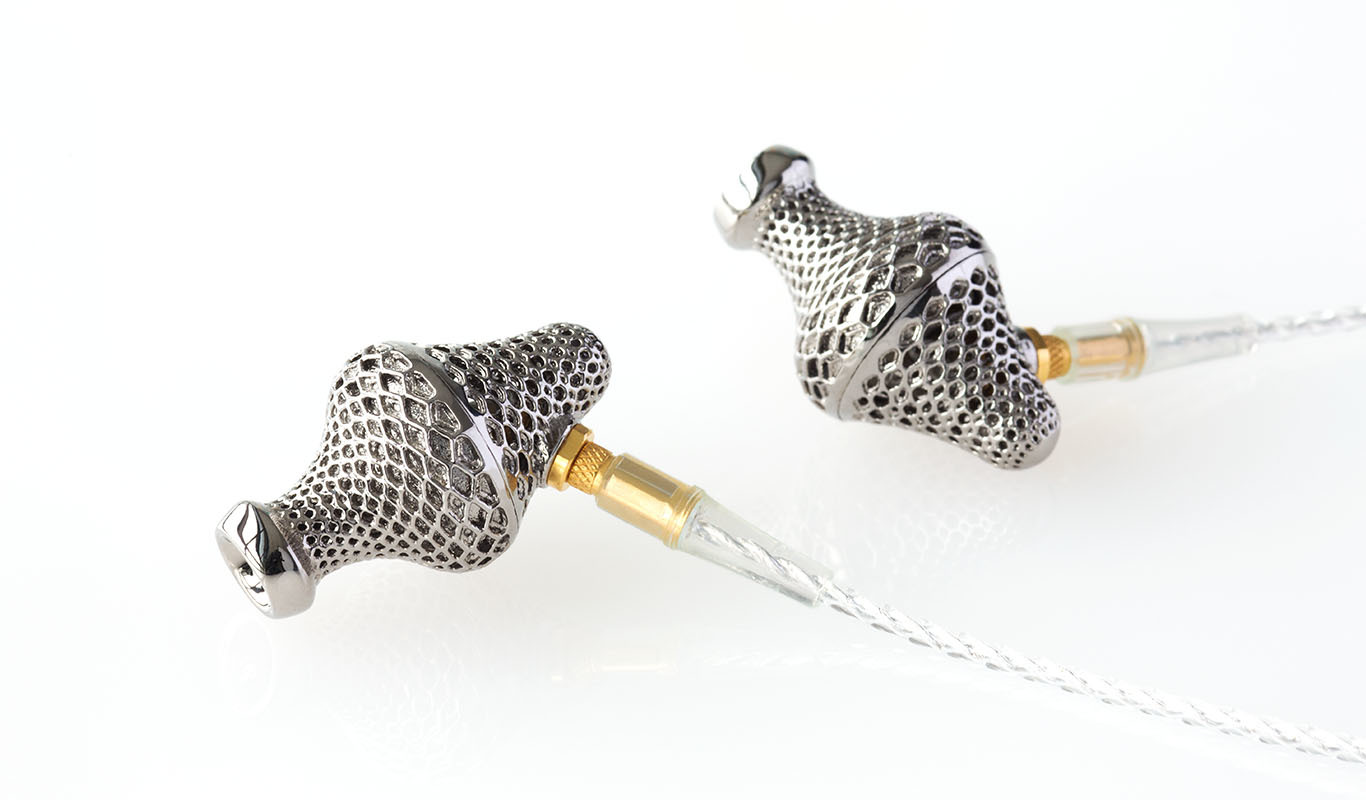
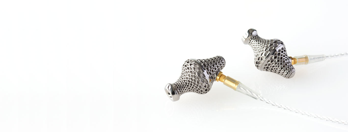
With a unique shape that can only be created using a 3D printer, a vast sound field never seen before is achieved.
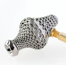
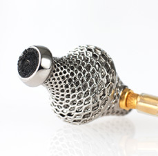
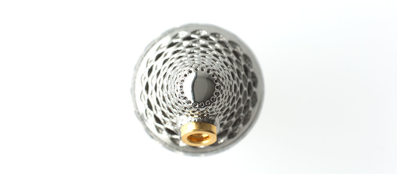
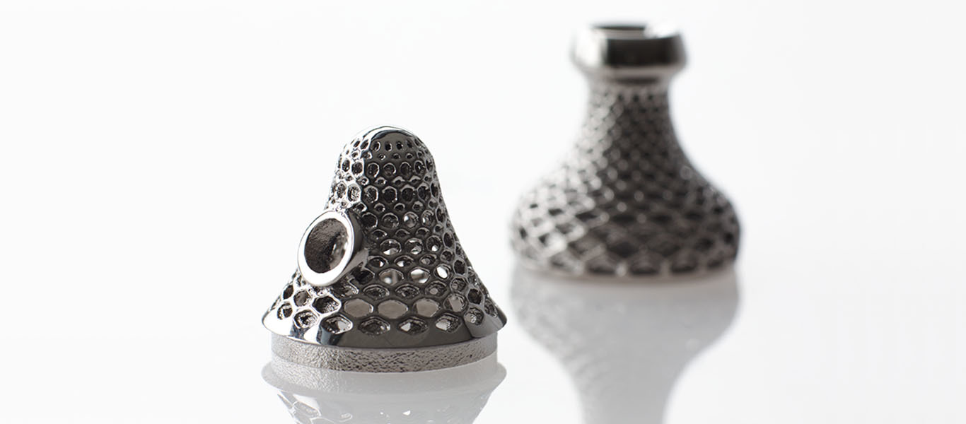
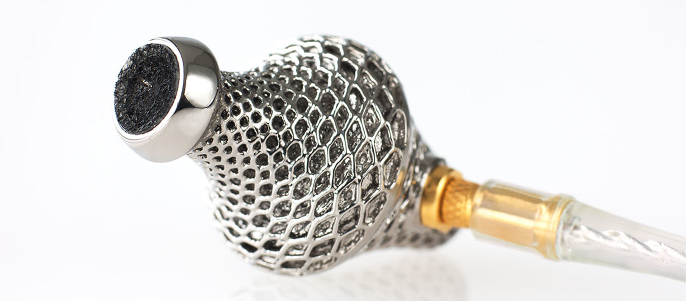
When using an open-type large-bore dynamic driver unit, it was difficult to lengthen the range of both high and low frequencies, and the spread of the bandwidth was limited. With LAB2, using a mechanical equalizer shaped using a 3D printer has achieved a form previously not possible with manufacturing methods up until now, and we've improved high frequency characteristics. The back has been made full open; the sound conduit at the front suppresses interference from the front and back of the diaphragm, resulting in an improvement in low frequency characteristics. With the mesh form on the outside of the housing, a very slight space between the auditory canal and the housing has been designed, and a natural sound field free from occlusion is realized. This special shape, the result of our pursuit of sound, was achieved using a 3D printer.
AWARD

VGP 2017 Summer
Life Style
2017, Japan
Life Style
2017, Japan

VGP 2017 Summer
Life Style
2017, Japan
Life Style
2017, Japan
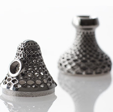
Titanium housing created using a 3D printer
Creating a number of prototypes showed us that to achieve the vast, true-to-life sound stage we aspired to,
the housing needed to meet the following conditions:
・ A mechanical equalizer on the front surface of the diaphragm
・ The back of the driver unit being open to a large degree
・ A space between the housing and the user's auditory canal was necessary
When we conducted simulations regarding the optimal form for the mechanical equalizer based on the points above gleaned through the prototypes, we realized that such a form could only be achieved using a 3D printer. To create a complicated metal form using a 3D printer, however, required a great deal of knowledge and know-how regarding molding. The image of this thing called a printer is that the 3D data sent to it is created with the press of a button, but this is not actually true. With a 3D metal layering printer, a level layer of 30μ metal powder is irradiated using a laser and fused together to create a form. Metal powder is layered onto this with a high degree of accuracy; the same process is repeated over a long period of time to create a shape. Because of this, changes to the form owing to the heat created during the molding process need to be considered, or a high level of precision will not be possible. It is necessary to redraw the 3D data drawn up by the designer into data and a form for molding. There is no set way of doing this; it is necessary to create a test piece and take this data into account to determine a form.
Here, with the cooperation of NTT Data Engineering Systems (NDES), we were able to create a mechanical equalizer whose thinnest section was just 0.2mm. NDES engineers took into consideration all of the conditions necessary in terms of sound quality together with those necessary for high-precision molding – including heat radiation - and derived the most appropriate form for the mesh covering the surface.
The mesh form on the outer surface is not just for the sake of sound quality;
it is also a form that heightens molding precision.
In order to derive the most appropriate form, engineers from NDES and from our own company shared their ideas, shaping and modeling over and over. A lot of know-how very difficult to put into words was necessary during this process. It is said that if you have a 3D printer, you don't need artisan skills. In actual fact, shaping something using a 3D metal layering printer becomes possible only when you have an engineer known as a "3D shaping artisan". The reason you don't find products around you that have been molded using a 3D metal layering printer is because molding using such a printer is a mass of detailed know-how.
- Surface finish
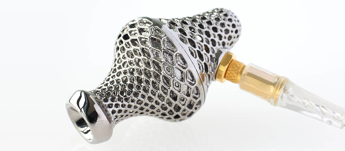
There is one more problem with respect to molding using a 3D printer, and that is the roughness of the surface. While titanium powder grains are extremely small at 3μ, a surface this rough causes pain when introduced directly into the ear. Conversely, it is better in terms of sound quality for the surface of the inner aspect of the mechanical equalizer to have a suitable roughness to it. To address the complicated problem of different degrees of roughness depending on location, we teamed up with a chemical manufacturer and created numerous prototypes; in doing so, we discovered the most suitable processing method for finishing the surface of the titanium after it had been molded using the 3D printer. The outer aspect was made smooth, while an appropriate level of roughness was left on the inner aspect and a chemical treatment was applied. Maintaining a high degree of precision at the same time made for a very complicated job, and a long period of time was spent accomplishing this. Because of this, the glossy finish of the outer aspect currently ranks as one of the smoothest in the world for titanium forms shaped by 3D printers.
There is one more problem with respect to molding using a 3D printer, and that is the roughness of the surface. While titanium powder grains are extremely small at 3μ, a surface this rough causes pain when introduced directly into the ear. Conversely, it is better in terms of sound quality for the surface of the inner aspect of the mechanical equalizer to have a suitable roughness to it. To address the complicated problem of different degrees of roughness depending on location, we teamed up with a chemical manufacturer and created numerous prototypes; in doing so, we discovered the most suitable processing method for finishing the surface of the titanium after it had been molded using the 3D printer. The outer aspect was made smooth, while an appropriate level of roughness was left on the inner aspect and a chemical treatment was applied. Maintaining a high degree of precision at the same time made for a very complicated job, and a long period of time was spent accomplishing this. Because of this, the glossy finish of the outer aspect currently ranks as one of the smoothest in the world for titanium forms shaped by 3D printers.
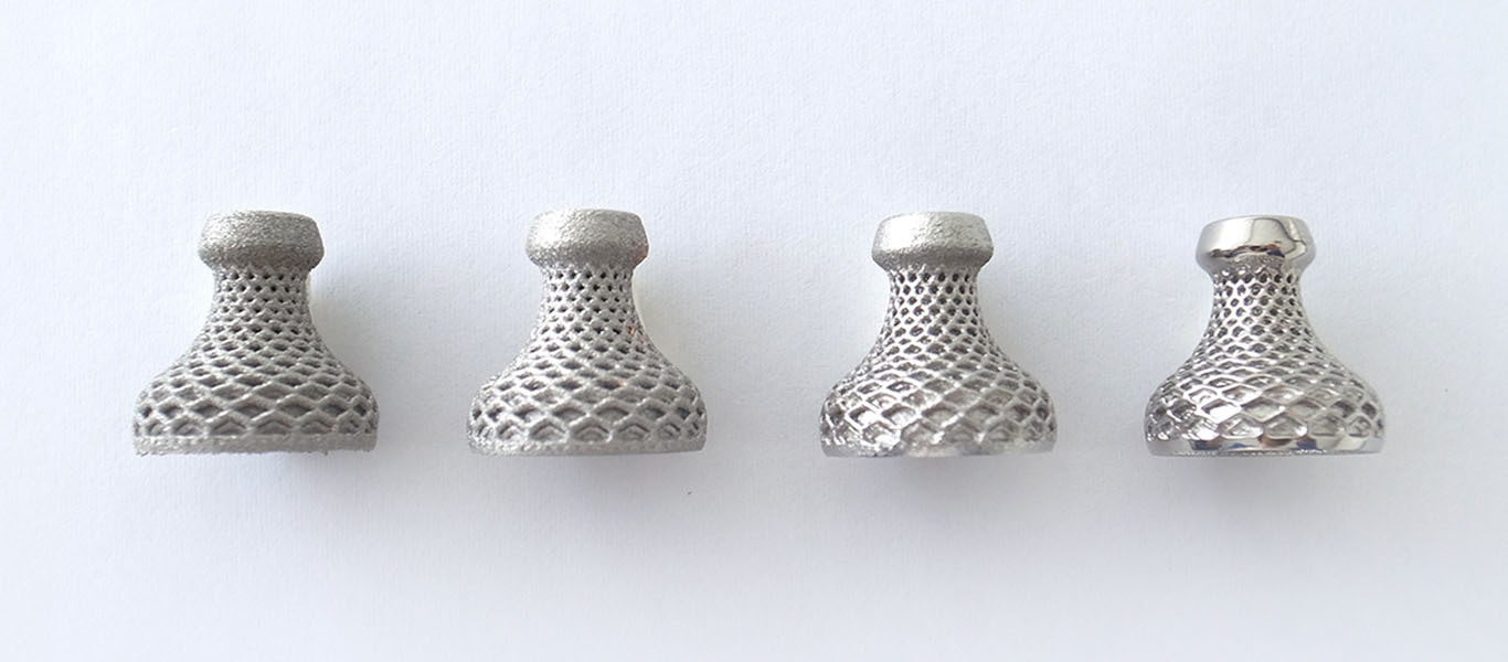
Mechanical equalizer integrated housing
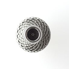
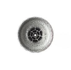
The mechanical equalizer has been positioned at the front of the diaphragm so as to prevent a decline in high-frequency characteristics owing to interference, as well as to undertake improvements in transient characteristics by applying just the right amount of pressure to the diaphragm. Both the plate thickness of the sound output aperture – the concentric equalizer – and the gap are 0.2mm. This form is one that can only be achieved using a 3D printer. Through simulations based on the principle prototype and numerous repetitions of the prototype – measurement – trial listening sequence, we were able to find a final form that met our aim.
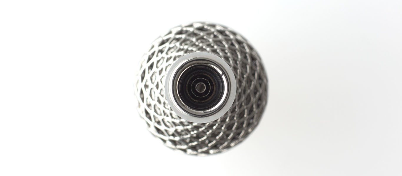
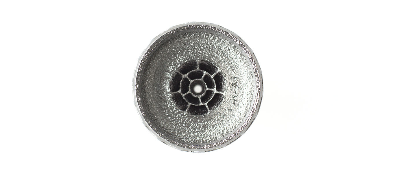
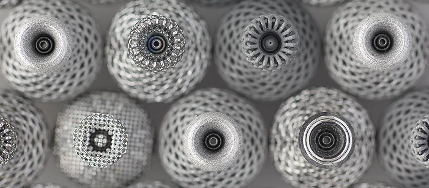
Mesh form with high degree of openness
With its high aperture ratio, the mesh form contributes to sufficient bass tones and to the spread of the sound stage. There were a number of prerequisites in determining this form, and as with the mechanical equalizer, seeking an optimal value was extremely difficult. The following conditions needed to be considered:
・ Sound quality
・ Procurement of the necessary aperture ratio
・ Distortions due to heat during the 3D molding process
・ The degree of stability of the aperture ratio during dissolution through chemical polishing
・ Sufficient strength for use with an MMCX connector
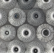
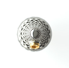
The form that considered all of these conditions was a double-layered mesh form, where a second mesh form is hidden underneath the first mesh form that can be seen from the outside.
15mm diameter newly developed dynamic driver unit
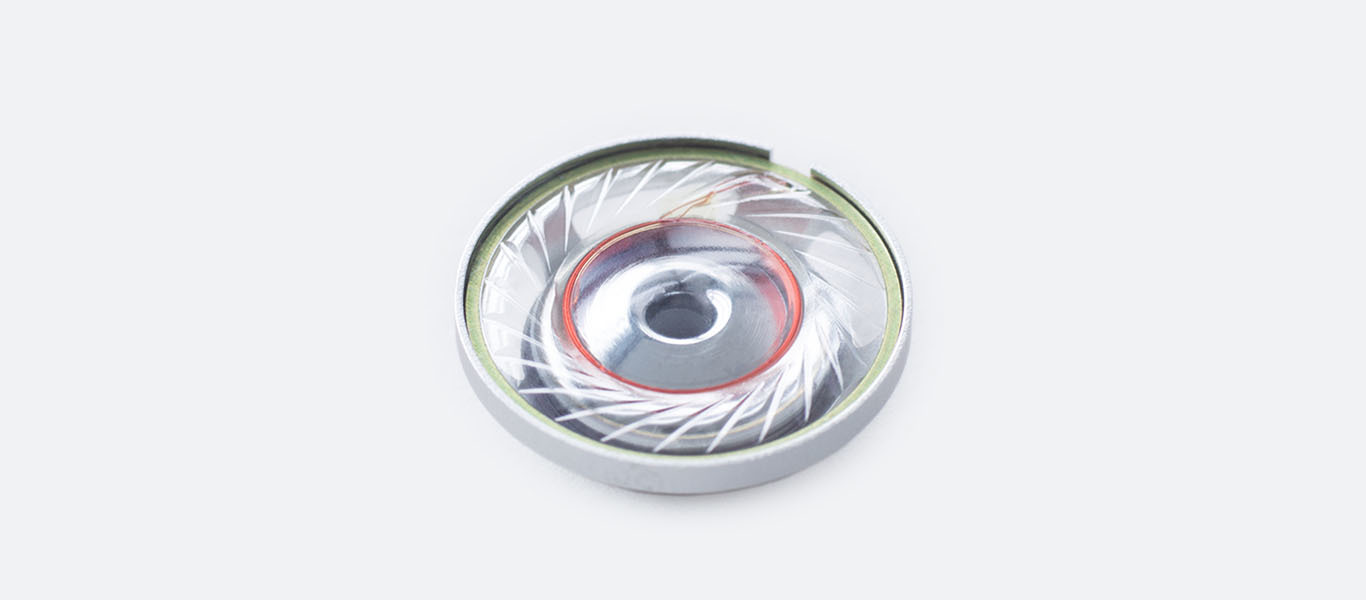
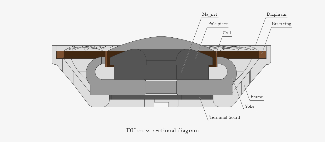
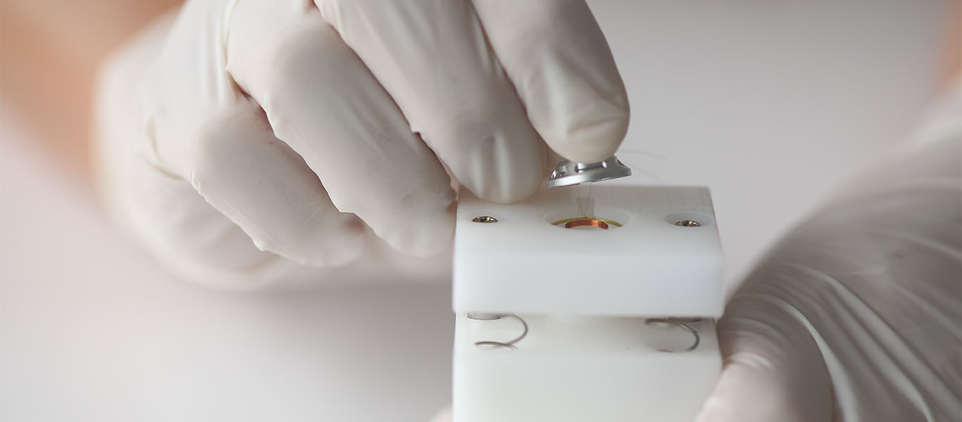
In line with the concept of achieving a vast, true-to-life sound stage through open earphones, we developed a new dynamic driver unit with a 15mm diameter. Having conducted listening trials, pure iron was employed for the yoke and the pole piece making up the magnetic circuit together with the neodymium magnet. As a result of having conducted repeated simulations to raise the density and the parallelism of the magnetic flux of the gap, the yoke was given a large curved surface, a shape never seen before. To suppress unnecessary vibrations, the frame was cut from an extremely strong aluminum magnesium alloy. For true-to-life sound, the diaphragm of the earphones needed to be lightweight, and with this thought at the forefront, PET with a thinness of 6μ was employed in place of the more than 12μ thickness usually used. Since we possess manufacturing know-how regarding the shaping of the diaphragm and adhering it to the voice coil
in-company, it is possible for us to employ such a thin, difficult to produce diaphragm.
We conduct not only the assembly but also the manufacturing of the driver unit at our head office in Kawasaki. We conduct a 124 level separation on these driver units, and use only a fraction of those manufactured. The drivers that are used are subjected to a rigorous filtering process,
and left and right pairings are implemented.
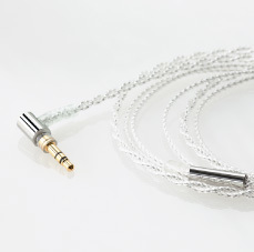
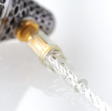
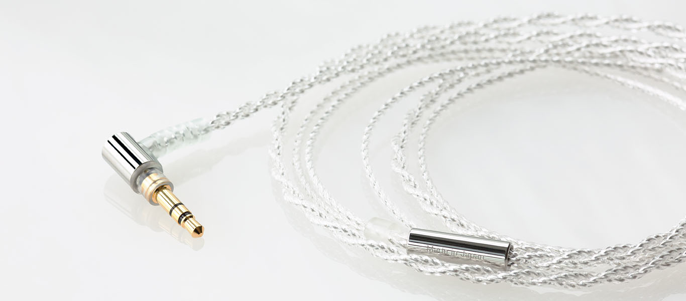
MMCX Connector&Original high purity OFC silver coated cable
We've used high-precision MMCX connectors from a famous Swiss manufacturer. We've used high-purity OFC silver coated cables that provide a wide sound stage. These jointly-developed cables were originally designed by and are currently manufactured by the well-renowned Junkosha corporation for the purpose of being used with the supercomputer "Kei" due to their fast signal transmission speed. The insulator film is made from PFA which was also developed by Junkosha who used their extensive know-how through the JUNFLON® brand to create the ultimate in low-permittivity material. The outer tube is made from PVC for maximum flexibility. The user will experience surprising flexibility that both makes the cable extremely easy to use as well as reducing the likelihood of microphonics. In addition, the MMCX plug and the 3.5 mm mini-plug have a tendency to disconnect so we've far exceeded the regular QA pass criteria of a 5,000-time bend test by changing the connection design to one that can withstand more than 50,000 bends.
Junkosha:
The Japanese corporation Junkosha develops and manufactures products such as high speed coaxial cables that boast the world's fastest transmission speed at 95% the speed of light, as well as cables for demanding fields such as marine and aerospace, healthcare and power generation facilities. These special cables require a high level of technology and center around fluoropolymers. Junkosha's cables are often called by the brand name JUNFLON® and have earned the tremendous trust of engineers requiring special-purpose cables.
* A total length of 1,200 km is now being used in supercomputers, and it takes longer for the electrons to flow through the cables than it does through the semiconductor. As the cable transmission speed is the limiting factor of the supercomputer speed, a substantial amount of development costs are spent in the pursuit of transmission speed.
* The connecting terminal has not been configured with a view to frequent connection and disconnection. Repeatedly connecting and disconnecting the terminal may lead to contact failure owing to wear or damage to the terminal; please ensure that any connection or disconnection is limited to situations of cable breakage or when the cable is replaced with other final cables that are sold separately.
Production at our own company factory in the pursuit of precision
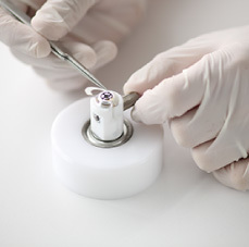
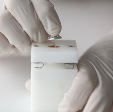
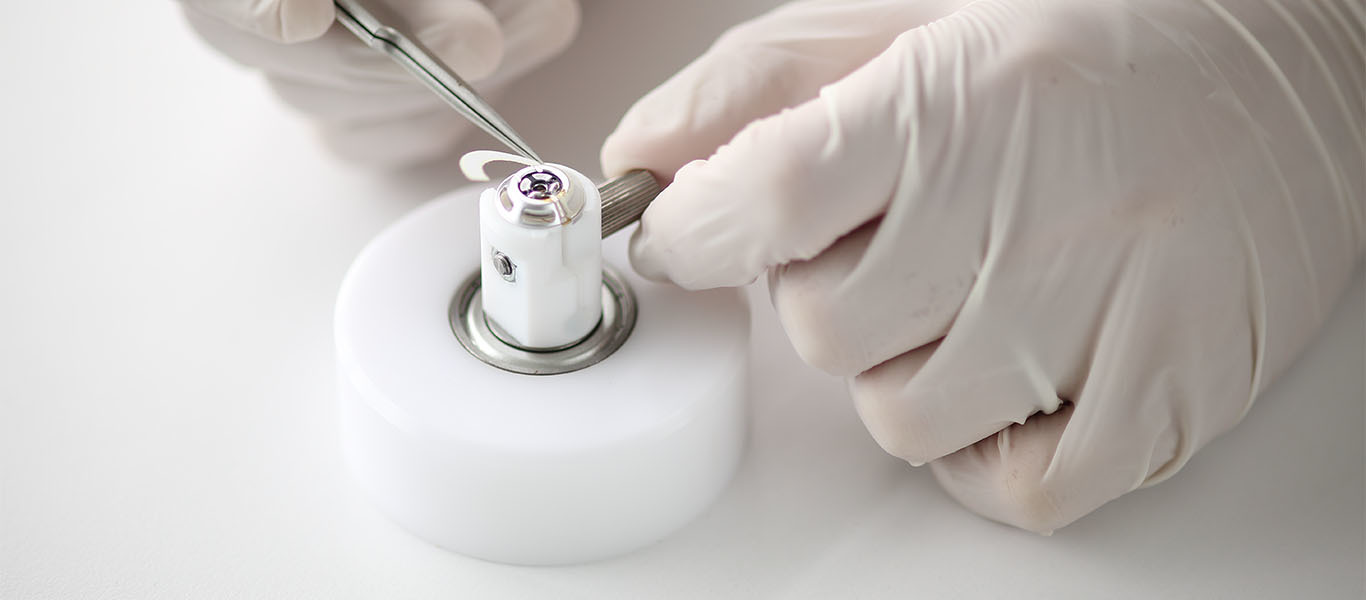
We conduct the assembly of LAB II at our own head office in Kawasaki. Together with the precision of individual parts, the precision involved in the assembly process depends on the precision of the tools known as jigs that assist in the assembly process. So as to be able to fine-tune even the slightest of irregularities in jig precision during the assembly process, we design and manufacture production jigs and measurement jigs ourselves. By undertaking everything from jig production through to product assembly in-house,
we maintain the high quality of our products.
Note : A mesh filter is fitted to the sound conduit of the product.
we maintain the high quality of our products.
Note : A mesh filter is fitted to the sound conduit of the product.
Specifications
- Product code
- FI-LAB02
- Housing
- Created using a 3D printer, 64 titanium polished finish
- Driver
- 15mmΦ dynamic
- Connector
- MMCX
- Sensitivity
- 110dB
- Impedance
- 22Ω
- Weight
- 31g
- Cord length
- 1.2m
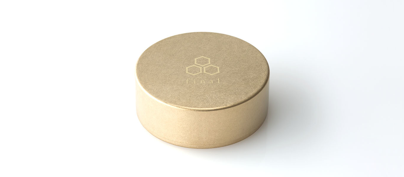
Accessories
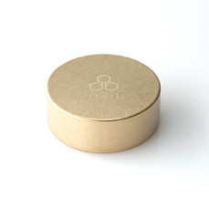
Brass carry case, Replacement adhesive dust filter
How to wear the earphones
Confirm the L and R labels on the left and right bushes. Holding the housing, insert the product into both ears using a slight twisting motion. While playing music, move the section inserted into the ears one at a time to find the position that is the most well-balanced for you. The best fit is one where there is a slight gap between the earphone and the auditory canal. Some people may find a positioning where the earphones are slightly loose to be preferable. Optimal positioning may differ between the left and the right ear. The best position is where there is a vast sound stage and the bass tones are not too strong, where there is a natural sound. It may take time at first to find the best position, but your ears will become accustomed to the fit and to the sound that is right for you, and you will easily be able to adjust the earphones from then on.
* There is a protrusion on the inner aspect of the left bush (L) so as to be able to
distinguish between left and right in the dark.
* LAB II is designed in such a way that sound quality differs greatly with positioning and fit.
* Usually, the shape of a person's ears differs greatly between left and right. As such, the optimal position
for the earphones differs between the left and right ears.

Sound quality reviews
Smooth, soft, mellow sound across all bands. An overwhelmingly wide range and earphones with forward positioning that is hard to achieve are characteristic of this model.
We encourage you to give your attention to the "airy feel" of musical instruments and vocals.
A vividness bound to surprise you will unfold before your eyes.
We encourage you to give your attention to the "airy feel" of musical instruments and vocals.
A vividness bound to surprise you will unfold before your eyes.
User reviews
With its wide sound field that gives you the sensation of listening to music in a hall, LAB II is really well-suited to orchestral music. With its soft sound, I think that it's also suited to jazz music. These earphones let you enjoy a sense of reality, as though you were listening to live music. It can't be avoided, but the only problem I would say is the price.
Overall, the balance is good, and they are wonderful earphones.
Overall, the balance is good, and they are wonderful earphones.
(male, 20-29 years)
I was a bit worried about whether or not I could fit them into my ears properly, but I had no problems at all. They fit very well.
It was a bit difficult to distinguish left from right.
Low ranges emerge clearly and have a straight draw. Make for easy listening (maybe because the diaphragm is thin?).
It's pretty obvious, but there's a lot of sound leakage.
Usually, I use the F3100 model (I know I shouldn't compare), and these are wonderful too.
(male, 30-39 years)
